In the intricate world of Australian process plants, from the vast LNG facilities of the North West Shelf to the advanced chemical processing plants in Victoria, one document reigns supreme in its importance and ubiquity: the Piping and Instrumentation Diagram (P&ID). More than just a blueprint, the P&ID serves as the operational roadmap, the single source of truth for process engineers, operators, and maintenance teams alike. It meticulously details the complex network of equipment, piping, instrumentation, and control systems that define a process, acting as the vital communication link across all stages of a plant’s lifecycle.
For process engineers working within Australia’s demanding industrial landscape, a deep understanding of P&IDs is not just beneficial – it’s foundational. These diagrams are the bedrock upon which design reviews are conducted, safety studies like HAZOP are performed, operator training programs are built, and maintenance procedures are planned. An accurate, clear, and consistently updated P&ID is synonymous with a safe and efficient operation, directly impacting everything from project timelines and budgets to environmental compliance and overall plant reliability within the Australian context. Conversely, a poorly developed or outdated P&ID introduces significant risks, potentially leading to costly downtime, safety incidents, and regulatory non-compliance, issues that are particularly critical in Australia’s heavily regulated industries.
This comprehensive guide is specifically tailored for Australian process engineers. We will delve into the essential elements of P&IDs, decode the standardised symbology crucial for interpretation in the Australian engineering community, explore the document’s pivotal role throughout the entire plant lifecycle within Australian projects, examine its indispensable function in process safety management under Australian regulations, and finally, look towards the future of intelligent P&IDs and their growing importance in the digitalisation of Australian industry.
Decoding the Language of the Plant: Understanding P&ID Symbology in Australia
The power of a P&ID lies in its ability to communicate complex information through a standardised visual language. Primarily adhering to the ANSI/ISA-5.1-2022 standard, widely adopted and recognised within Australian engineering practices, this symbology ensures that a process engineer in Perth can readily understand a P&ID developed in Melbourne, fostering effective collaboration and knowledge sharing across the Australian process industries.
Visual Representation of Equipment
Each major component within a process plant is represented by a specific symbol, providing an immediate visual cue to its function. Familiarity with these symbols is fundamental for any Australian process engineer working with P&IDs.
- Pressure Vessels and Storage Tanks: Typically depicted as cylindrical shapes (horizontal or vertical), these symbols often include representations of internal components crucial for their operation in Australian process conditions, such as demisters (important in gas processing plants), baffles (common in mixing tanks), and vortex breakers (critical in pump suction lines).
- Heat Exchangers: Given the diverse temperature control needs in Australian industries (from the cold of LNG processing to the heat of mineral smelting), various symbols represent different types like shell-and-tube (most common), plate-and-frame (increasingly used for efficiency), and air coolers (essential in arid regions). The separate flow paths for the process and utility fluids (like cooling water or heating medium) are always distinctly shown.
- Pumps and Compressors: The standard circular symbol with a directional outlet is used universally. Variations within the circle indicate the type – centrifugal (common for large flow rates), positive displacement (for high pressures or viscous fluids), and axial (often seen in compressor applications).
- Distillation Columns and Towers: Critical in many Australian chemical and petrochemical processes, these are shown as tall vertical vessels with indicators for internal stages like trays or packing. Each column will have a unique identifier (e.g., T-101), vital for referencing in other documentation.
- Fired Heaters and Furnaces: Essential in oil refineries and some mineral processing, these symbols depict a combustion chamber, clearly indicating the heat input to the process fluid.
The Network of Pipes and Their Identifiers
Piping forms the essential connections between equipment. In Australian plant P&IDs, the information conveyed by the lines themselves and their associated tags is paramount.
- Distinguishing Line Types: Solid lines of varying thicknesses differentiate between major and minor process streams. Utility lines (steam, compressed air – vital in pneumatic systems common in older Australian plants, nitrogen – crucial for purging and inerting) are often represented by dashed or specifically coded lines, ensuring immediate recognition of their purpose within the system.
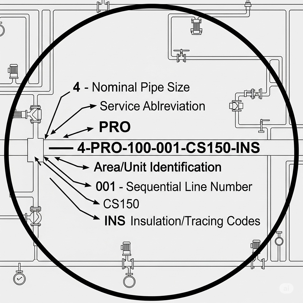
- Decoding the Line Tag: The line number or tag is the key identifier for any pipeline segment within an Australian plant. Its structured format provides a wealth of information at a glance:
- Nominal Pipe Size (NPS): Clearly indicating the diameter in inches (e.g.,
4"). - Service Abbreviation: A concise code specifying the fluid (e.g.,
PROfor Process,HYDfor Hydrocarbon,CWfor Cooling Water – particularly important in Australia’s often hot climate). - Area/Unit Identification: Defining the plant section or process unit (e.g.,
100). - Sequential Line Number: A unique number for that specific line within the unit (e.g.,
001). - Piping Specification: A crucial code (e.g.,
CS150) referencing a comprehensive piping specification document. This document, vital for material selection in often corrosive Australian environments, details the pipe material (e.g., Carbon Steel), pressure rating (e.g., Class 150), welding procedures, and applicable Australian Standards. - Insulation/Tracing Codes: Designators like
-INSfor insulation (critical for energy efficiency and personnel protection in Australia’s temperature extremes) or-HTRfor heat tracing (used to prevent freezing or maintain viscosity of fluids).
- Nominal Pipe Size (NPS): Clearly indicating the diameter in inches (e.g.,
An example of a complete Australian standard line tag: 4"-PRO-100-001-CS150-INS.
Controlling the Flow: Valve Symbology and Actuation
Valves are the workhorses of process control. Their symbols and the indication of their actuation methods are critical for understanding how the plant operates and is controlled in Australia.
- Valve Body Representations: Standard symbols clearly depict valve types: gate (for isolation), globe (for throttling – important in controlling flow rates in Australian processing), ball (another common isolation valve), check (preventing backflow, crucial in pump discharge lines), and butterfly (often used for large diameter lines).
- Actuator Indication: Symbols attached to the valve body denote how the valve is operated. Common types include manual (handwheel), pneumatic (diaphragm or piston – widely used for automated control), electric (motorised – becoming increasingly prevalent), and hydraulic. For control valves (essential for maintaining process parameters), a specific symbol with a connected actuator (often pneumatic) is used, signifying its role in an automated control loop managed by the plant’s control system (DCS or PLC systems common in Australian industry).
The Intelligence Layer: Instrumentation and Control Symbols in Australian Plants
Instrumentation is the nervous system of a process plant, providing the critical data for monitoring and control. The symbology, strictly governed by ISA-5.1 and consistently applied in Australian engineering, communicates the type, function, and location of each instrument.
- The Instrument “Bubble”: The circle (or sometimes a square for programmable logic controllers or other computer functions) indicates an instrument. A single solid line signifies a field-mounted device (directly on the process), a dashed line indicates a device located in an auxiliary location, and importantly for Australian control rooms, a double solid line often indicates a primary instrument located on the main control panel accessible to plant operators.
- Decoding the Tag Letters: The letters within the bubble provide a concise description of the instrument’s role. The first letter denotes the measured or initiating variable, and subsequent letters indicate the function(s) performed.
- Signal Lines: The type of line connecting instruments indicates the nature of the signal: solid for process connections (the physical tap into the pipe or vessel), dashed for electrical signals (common for transmitting sensor data to the control system), a line with diagonal slashes for pneumatic signals (still found in many established Australian plants), and a line with small circles for digital or data network communication (increasingly prevalent with modern distributed control systems – DCS).
Proficiency in deciphering this standardised symbology is a fundamental skill for any process engineer operating within Australia’s diverse range of process industries, enabling them to effectively understand, analyse, and contribute to the design and operation of complex plants.
The Evolving Role: P&IDs Across the Australian Plant Lifecycle
In the Australian project lifecycle, the P&ID is not a static deliverable; it’s a dynamic document that matures alongside the project, serving distinct but critical purposes at each stage, from the initial concept to the eventual decommissioning of a plant in Australia.
Conceptual and Front-End Engineering Design (FEED) in Australia
The journey begins with the Process Flow Diagram (PFD), which provides a high-level overview of the process. As the project advances into FEED, the P&IDs are developed, expanding upon the PFD by incorporating:
- All Secondary and Utility Piping: Detailing the connections for essential services like steam (widely used for heating in Australian industries), compressed air (for pneumatic tools and instruments), nitrogen (for purging and inerting), and cooling water (critical in Australia’s warmer climates).
- Primary Control Loops: Illustrating the basic automation strategies for key process variables (flow, level, pressure, temperature) that will be managed by the plant’s control system.
- Preliminary Valve Specifications: Indicating the types and approximate sizes of major isolation and control valves required for the process.
- Initial Line Sizing and Material Considerations: Providing a first pass at determining pipe diameters based on flow rates and flagging potential material requirements considering the often corrosive nature of process fluids in Australian mining and chemical operations.
At this crucial FEED stage, the P&ID becomes a cornerstone for early-stage cost estimation for Australian projects, informs preliminary plant layout studies considering Australian site conditions and regulatory requirements, and serves as the foundation for initial Hazard Identification (HAZID) workshops, a critical step in ensuring safety from the outset in Australian industry.
Detailed Design and Engineering for Australian Projects
The detailed design phase sees the P&ID evolve into its most comprehensive form, becoming the definitive reference document used by all engineering disciplines involved in the Australian project:
- Complete Instrument Specification: Every instrument is assigned a unique tag number (following Australian standard practices), and its specific type, range, accuracy, and installation details are finalised.
- Finalised Line Numbers and Piping Specifications: All line numbers are confirmed, and the precise piping specifications (material grade, wall thickness, flange rating, insulation requirements considering Australian temperature variations) are documented, referencing relevant Australian Standards.
- Integration of Safety Systems: Critical safety devices such as Pressure Relief Valves (PSVs), rupture disks, and Safety Instrumented Systems (SIS) loops are added with their specific setpoints, capacities, and logic diagrams, ensuring compliance with stringent Australian safety regulations.
- Incorporation of Vendor Data: Information from equipment suppliers (e.g., pump curves, vessel dimensions) is integrated into the P&ID and associated data to ensure accurate representation.
At this stage, the P&ID is typically “frozen” to provide a stable basis for mechanical equipment design, structural steel detailing, electrical power distribution design, and control system programming – all crucial elements of delivering a successful project in Australia. Rigorous revision control procedures, often mandated by Australian project management standards, are implemented to manage any necessary changes.
Construction and Commissioning in the Australian Context
During the construction phase in Australia, the P&ID serves as the primary reference document for the installation crews. It guides the physical placement and connection of every pipe, valve, and instrument on site, ensuring adherence to the approved design. During commissioning, process and instrumentation engineers use the P&ID to perform crucial system checks, conduct line walks to verify physical installation against the drawings, and perform loop checks to ensure the correct functionality of every control loop, verifying that sensor signals accurately drive the final control elements – all vital steps before a plant can safely start up in Australia.
Operation and Maintenance in Australian Plants
Once the plant is operational, the P&ID remains an indispensable tool for the Australian operations and maintenance teams:
- Operational Guidance: Operators rely on the P&ID to understand the process flow, identify critical control points, and troubleshoot operational upsets or deviations from normal conditions, crucial for maintaining stable and efficient production in Australian facilities.
- Maintenance Procedures: Maintenance technicians use the P&ID to locate specific equipment, identify necessary isolation points before performing maintenance tasks (a critical safety aspect under Australian WHS regulations), and understand the interdependencies of various components within the system.
Management of Change (MOC) in Australian Industry
Given the dynamic nature of industrial facilities in Australia, modifications and upgrades are common. A robust Management of Change (MOC) process, often mandated by Australian safety and environmental regulations, is essential. A core component of any MOC procedure is the mandatory update of the P&ID to accurately reflect any physical changes made to the plant. Maintaining an “as-built” P&ID that precisely mirrors the installed equipment and piping is a fundamental requirement for safety, regulatory compliance, and efficient future modifications within the Australian industrial landscape. Inaccurate or outdated P&IDs pose a significant safety risk and can lead to non-compliance with Australian standards.
The P&ID as a Pillar of Process Safety Management (PSM) in Australia
In Australia’s highly regulated process industries, an accurate P&ID is not merely a design or operational aid; it is a fundamental pillar of Process Safety Management (PSM) systems, often mandated by state and federal safety legislation. It forms the very basis for identifying, assessing, and mitigating hazards within a facility.
HAZOP (Hazard and Operability) Studies in Australia
The Hazard and Operability (HAZOP) study is a systematic and critical review process used to identify potential hazards and operational issues in a process plant. In Australia, HAZOP studies are a cornerstone of risk assessment, and the P&ID is the primary document that the multi-disciplinary HAZOP team (comprising process engineers with local Australian experience, plant operators familiar with Australian operating procedures, instrument engineers versed in Australian control systems, and safety specialists knowledgeable in Australian regulations) uses to systematically examine the process, node by node, applying standardised guidewords to process parameters to identify potential deviations and their consequences. The P&ID provides the essential visual and functional context for this critical safety review.
LOPA (Layer of Protection Analysis) in the Australian Context
Layer of Protection Analysis (LOPA) is a semi-quantitative risk assessment technique used to evaluate the adequacy of independent protection layers (IPLs) in place to prevent or mitigate hazardous events identified in a HAZOP study. In Australia, LOPA is often used to determine if the existing safeguards, visually represented on the P&ID (such as basic process control system alarms, operator intervention steps documented in Australian operating procedures, pressure relief devices sized according to Australian standards, and Safety Instrumented Systems designed to meet Australian safety integrity levels – SIL), are sufficient to reduce the risk to an acceptable level as defined by Australian risk management frameworks. The P&ID serves as the visual confirmation of these critical safety layers.
Safety Instrumented Systems (SIS) in Australian Process Plants
Safety Instrumented Systems (SIS) are critical automated safety functions designed to bring a process to a safe state upon detection of a hazardous condition. In Australian plants, these systems, comprising sensors, logic solvers (often PLCs certified to specific SIL levels), and final elements (like emergency shutdown valves – ESDVs), are clearly identified on the P&ID, often with distinct symbology (e.g., instrument bubbles with a border or specific tag prefixes indicating their safety function) to differentiate them from regular process control instrumentation. This clear visual representation on the P&ID is crucial for ensuring that all personnel understand the safety-critical nature of these systems and their role in preventing major incidents in accordance with Australian safety regulations.
The Digital Future: Intelligent P&IDs in Australian Industry
The traditional 2D CAD-based P&ID, while still prevalent in many established Australian facilities, is gradually being replaced by Intelligent or Smart P&IDs. This digital evolution represents a significant leap forward in how process plants are designed, managed, and maintained across Australia.
The Essence of a Smart P&ID
A Smart P&ID is not merely a digital drawing; it is a database-centric representation of the process. Every symbol, every line, every piece of information on the diagram is linked to underlying data stored in a relational database. This creates a dynamic and interconnected “digital twin” of the process. When a process engineer in Australia clicks on a pump symbol in a smart P&ID, they can instantly access a wealth of associated information, including the pump’s datasheet (specifications relevant to Australian operating conditions), its serial number, its maintenance history within the Australian plant’s CMMS (Computerised Maintenance Management System), and its electrical motor details. Similarly, a change made to a line specification (e.g., material upgrade due to corrosion concerns in a coastal Australian environment) is automatically propagated throughout the database and reflected in any related reports.
Tangible Benefits for Australian Process Engineers and Operators
The adoption of intelligent P&IDs offers numerous advantages for the Australian process industries:
- Enhanced Data Consistency and Accuracy: Eliminates the inconsistencies that can plague traditional drawing sets, ensuring that the information presented on the P&ID aligns with equipment lists, valve schedules, and instrument databases, reducing the risk of errors in design, procurement, and construction within Australian projects.
- Streamlined Revision Control and Management of Change (MOC): Makes the process of updating P&IDs following plant modifications (a frequent occurrence in Australia’s evolving industrial landscape) significantly more efficient and less prone to errors, ensuring that the digital documentation accurately reflects the physical plant for safety and regulatory compliance.
- Automated Report Generation: Enables the rapid creation of various reports directly from the P&ID database, such as lists of all tagged equipment, valve inventories, line lists with complete specifications (crucial for material take-offs in Australian projects), and instrument indexes, saving significant time and improving accuracy.
- Seamless Integration with 3D Plant Models: Facilitates a tighter integration between the 2D P&ID and the 3D physical model of the plant, allowing for clash detection and spatial coordination, which is particularly valuable in complex brownfield modifications common in Australia.
- Improved Lifecycle Data Management: Transforms the P&ID into a central repository for asset information throughout the plant’s entire lifecycle in Australia, linking to maintenance records, operational data historians, and safety management systems, providing a holistic view of asset performance and history.
Leading software platforms like AVEVA E3D & Diagrams and Hexagon Smart P&ID, with their strong presence and support networks in Australia, are driving this digital transformation, empowering Australian process engineers with the tools to create and manage intelligent plant documentation.
Navigating the Path to Excellence: Best Practices for Australian P&ID Management
To maximise the value and ensure the integrity of P&IDs within Australian process plants, adherence to established best practices is crucial:
- Establish a Solid Foundation with PFDs and H&MBs: Always develop P&IDs based on approved Process Flow Diagrams (PFDs) and Heat and Mass Balances (H&MBs) to ensure a consistent and accurate representation of the underlying process design principles relevant to Australian conditions and throughput requirements.
- Implement and Enforce Standardised Symbol Libraries and Tagging Conventions: Adopt and strictly adhere to industry-standard (preferably ISA compliant) symbol libraries and consistent tagging conventions across all projects within your Australian organisation. This ensures clarity, reduces ambiguity, and facilitates seamless understanding across different engineering teams and plant sites in Australia.
- Prioritise Clarity, Readability, and Logical Layout: Design P&IDs with a clear and logical flow, typically following a left-to-right or top-to-bottom progression of the process. Employ appropriate spacing, avoid overcrowding of symbols and annotations, and utilise off-page connectors effectively to link related sections across multiple drawing sheets. The primary goal should be to create diagrams that are easy to follow and understand for all stakeholders in the Australian context.
- Institute a Multi-Stage Rigorous Checking and Approval Process: Implement a comprehensive quality assurance process that includes multiple levels of review, including self-checks by the drafter, peer reviews by experienced process or instrumentation engineers familiar with Australian standards, and inter-disciplinary checks to ensure consistency with other engineering deliverables. Formal sign-offs and approval workflows are essential before P&IDs are issued for design, construction, or operation in Australia.
- Maintain Strict Revision Control and Traceability: Employ a robust revision management system that clearly tracks all changes made to P&IDs over the plant’s lifecycle. Each revision should be uniquely numbered or lettered, dated, and accompanied by a brief description of the changes made and the reason for the revision. Ensure that all superseded versions are archived and readily retrievable if needed for historical reference or audit purposes within the Australian regulatory framework.
Conclusion: The Unwavering Importance of P&IDs in Australian Process Engineering
In the demanding and highly regulated process industries of Australia, Piping and Instrumentation Diagrams (P&IDs) stand as the indispensable visual language of the plant. They are the bedrock upon which safe, efficient, and compliant operations are built, the crucial communication tool that bridges the gap between engineering design and operational reality across the diverse range of Australian industrial facilities.
For Australian process engineers, a mastery of P&IDs – from the fundamental understanding of symbology to the strategic implementation of intelligent digital platforms and adherence to stringent best practices in their management – is not just a professional advantage; it is a fundamental requirement for success and for ensuring the continued safety and prosperity of Australia’s vital process industries. As technology continues to advance, the evolution of the P&ID into a smart, data-driven asset will only amplify its importance, solidifying its role as the unwavering blueprint of modern Australian industry.
At The Next Rex, we provide expert mechanical drafting services, including the development and management of high-quality, intelligent P&IDs tailored to the specific needs and regulatory requirements of Australian process plants. Our commitment to accuracy, clarity, and compliance ensures that your operations are built on a solid foundation of reliable documentation. Contact us to discuss how our expertise can support your next project in Australia.
