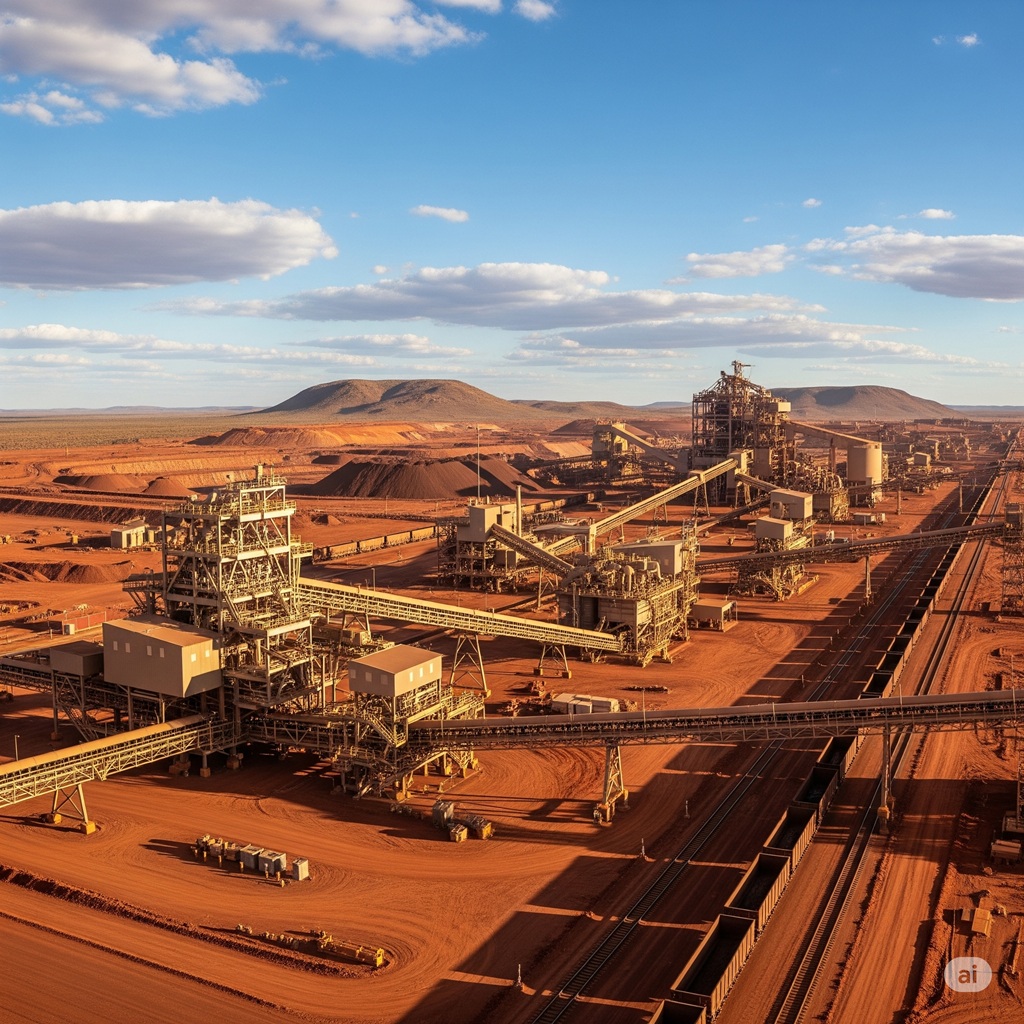
In the high-stakes world of Western Australia’s mining and manufacturing sectors, precision isn’t just a goal; it’s a prerequisite for survival. On a remote Pilbara mine site or a bustling Perth-based manufacturing floor, every second of downtime costs a fortune, and every compromise on safety can have catastrophic consequences. These are environments where equipment operates under immense stress, in some of the harshest conditions on earth. In this context, the discipline of mechanical drafting transcends the simple act of creating drawings. It becomes a critical function of risk management, operational efficiency, and asset lifecycle integrity.
The success of a multi-million-dollar plant expansion, a critical brownfield retrofit, or the development of a new automated production line hinges on the quality and accuracy of the technical documentation that underpins it. Sub-par mechanical drafting—riddled with inaccuracies, clashes, or a lack of detail—is a direct threat to project timelines, budgets, and safety. Conversely, exceptional mechanical drafting, delivered by a team that understands the specific demands of these heavy industries, is the foundation for seamless fabrication, efficient construction, and reliable, long-term operation.
This guide is a deep dive for the professionals who build and run WA’s economic engine: the project managers, mechanical and process engineers, and operations leaders. We will explore the specialised disciplines of mechanical drafting in this unique context, the transformative impact of digital technology, the critical importance of compliance, and what distinguishes a truly valuable drafting partner from a simple service provider.
Section 1: More Than Lines on a Page: Defining Mechanical Drafting for Heavy Industry
When discussing mechanical drafting in the context of WA’s resources and manufacturing sectors, it’s crucial to differentiate it from generalist or product design drafting. We are not talking about small consumer goods; we are talking about the design and documentation of massive, complex, and often bespoke systems designed for maximum durability and performance.
Mechanical drafting here is the specialist discipline of creating a complete and unambiguous set of technical documentation that communicates every detail of a mechanical component or system. It is the bridge between the engineer’s design calculations and the fabricator’s workshop, the installer’s construction site, and the maintenance team’s daily reality. Its outputs are the lifeblood of any project.
Key Outputs in Industrial Mechanical Drafting:
- General Arrangement (GA) Drawings: These are the master drawings that show the overall layout of the equipment or system. They illustrate the spatial relationships between major components, their position relative to structural elements (like columns and floor slabs), and key operational and maintenance envelopes. For a manager or engineer, the GA provides the high-level overview of how everything fits together.
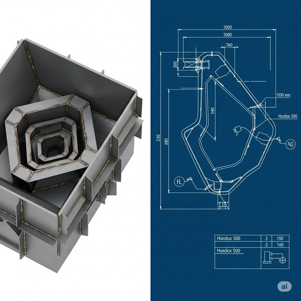
- Detailed Fabrication Drawings: Also known as shop drawings, these are the heart of the drafting process. They are highly detailed, fully dimensioned drawings of individual components (like a conveyor pulley frame or a specific chute plate) that provide a fabricator with all the information they need to manufacture the part. This includes material specifications, exact dimensions and tolerances, weld details, surface treatment requirements, and machining instructions.
- Piping & Instrumentation Diagrams (P&IDs): A P&ID is a schematic representation of the entire process flow. It shows how all the equipment (pumps, tanks, vessels) is interconnected by piping, along with all the instrumentation and control devices. It is a fundamental document for process engineers, operators, and safety reviews (like HAZOP studies).
- 3D Equipment Modelling: Before any 2D drawings are produced, modern drafting involves creating a detailed and accurate 3D model of the equipment or system. This intelligent model is the single source of truth from which all other drawings and data are derived.
- As-Built Documentation: After construction and commissioning, the original drawings are updated to reflect any on-site modifications. This “as-built” or “as-installed” set of documents is critically important for the ongoing maintenance, future modifications, and eventual decommissioning of the asset. Inaccurate as-builts are a major source of frustration and risk for operations teams.
The quality of these documents directly impacts project cost, schedule, and safety. An error in a fabrication drawing can lead to a multi-tonne component being manufactured incorrectly, causing weeks of delays and significant financial loss while it is rectified.
Section 2: The Core Disciplines of Mechanical Drafting for WA’s Resources Sector
WA’s heavy industry is not monolithic. The challenges of drafting a materials handling system for an iron ore mine are different from those for a high-pressure piping system at an LNG facility or a custom machine for a manufacturing plant. A truly competent drafting partner must have proven expertise across several specialised disciplines.
Fixed Plant & Materials Handling
This is the backbone of the mining industry. It involves the design and detailing of equipment used to move and process millions of tonnes of material.
- Focus Areas: Conveyor systems, transfer chutes, screen and crusher support structures, hoppers, and bins.
- Drafting Priorities: The primary focus is on durability, reliability, and maintainability. Drawings must include meticulous detail on:
- Wear Packages: Specifying the correct type, thickness, and attachment method for wear-resistant liners (e.g., chromium carbide, ceramics) inside chutes and hoppers is critical for extending asset life.
- Structural Integrity: While separate from the main structural drafting, mechanical supports and frames must be detailed for robustness to handle immense dynamic loads.
- Maintenance Access: Drawings must show clear access platforms, lifting points, and adequate space for replacing components like conveyor rollers or screen mats. This is a key part of “Safety by Design.”
Piping Systems & Spooling
Process plants in mining, oil and gas, and manufacturing rely on complex networks of piping to transport fluids and gases, often under high pressure and at extreme temperatures.
- Focus Areas: Process piping design, high-pressure lines, utility lines (air, water), and the generation of pipe spool drawings.
- Drafting Priorities: Precision and compliance are paramount.
- P&ID Adherence: The 3D piping model and drawings must be a 100% accurate representation of the approved P&ID.
- Pipe Spool Drawings: To accelerate site installation, piping systems are prefabricated in workshops into manageable sections called “spools.” The drafter creates an individual, fully detailed drawing for each spool, including all pipes, fittings, flanges, and valves, with a complete bill of materials. Accuracy here is essential for preventing rework.
- Compliance to AS 4041: All drafting for pressure piping must adhere to the stringent requirements of this Australian Standard.
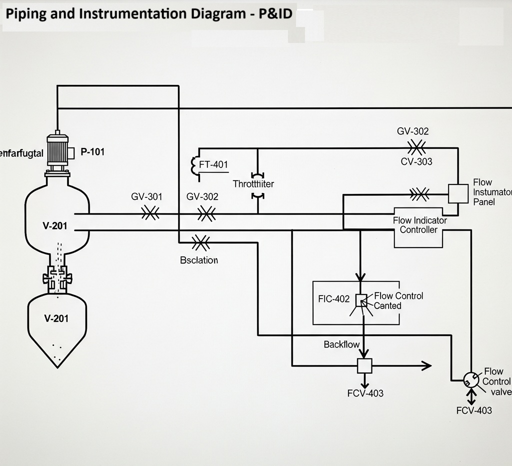
Piping and Instrumentation Diagram – P&ID
Pressure Vessels & Tanks
The storage and processing of fluids and gases under pressure requires vessels designed and fabricated to the highest safety standards.
- Focus Areas: The detailed design drafting of pressure vessels, storage tanks, and heat exchangers.
- Drafting Priorities: Safety is the absolute number one priority. The fabrication drawings must be meticulously detailed to meet the requirements of AS 1210 – Pressure vessels. This includes specifying:
- Plate material grades and thicknesses.
- Nozzle details, locations, and orientations.
- Weld preparation details and welding procedures.
- Requirements for non-destructive testing (NDT).
- Saddle or leg support details. The drafter works in close collaboration with the mechanical engineer to ensure every detail of the design calculations is accurately reflected in the workshop drawings.
Machine Design & Reverse Engineering
Both mining and manufacturing sectors often require custom machinery or modifications to existing equipment to solve unique problems or improve productivity.
- Focus Areas: Creating fabrication drawings for new, bespoke equipment; modifying existing machinery; and reverse engineering obsolete or difficult-to-source components.
- Drafting Priorities: This requires a combination of creativity and technical rigour. For reverse engineering, the process involves carefully measuring an existing component (using callipers, micrometres, or 3D scanners) and creating a full set of manufacturing drawings from scratch, including selecting appropriate modern materials and specifying tolerances.
Expertise across these disciplines is what allows a drafting service to be a true partner to industry, providing comprehensive solutions rather than just isolated drawings.
Section 3: The Digital Transformation: From 2D to Intelligent Digital Twins
For decades, the output of drafting was a 2D drawing on paper or a screen. Today, that 2D drawing is merely one output from a far more powerful and valuable asset: the intelligent 3D model. For WA’s complex industrial operations, embracing this digital transformation is essential for staying competitive.
The Power of the 3D Intelligent Model
The Power of the 3D Intelligent Model
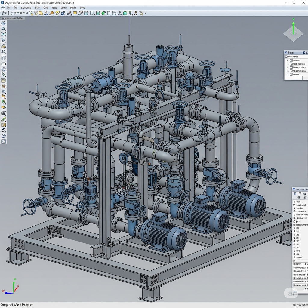
Modern mechanical drafting is performed using powerful 3D parametric modelling software like Autodesk Inventor or SolidWorks. This approach offers huge advantages over traditional 2D CAD:
- Unambiguous Visualisation: A 3D model allows everyone—from the project manager to the maintenance fitter—to see the equipment exactly as it will be built. You can rotate it, zoom in, and cut sections to understand complex areas, eliminating the misinterpretations that are common with 2D drawings.
- Automated Interference Checking (Clash Detection): This is a game-changer. The 3D mechanical model can be combined with models from other disciplines (structural, electrical, piping). The software can then automatically analyse the combined model and identify every single location where components clash—for example, a pipe running through a steel beam or an electrical cable tray hitting a piece of machinery. Finding and fixing these clashes in the digital model costs virtually nothing; finding them during construction can cost hundreds of thousands of dollars and cause weeks of delays.
- Data-Rich Environment: The model is more than just geometry. Each component can have data attached to it, such as part number, material, weight, supplier, and maintenance schedule. This “I” in BIM (Building Information Modelling) is the key to unlocking further value.
The Next Frontier: Digital Twins for WA Operations
A digital twin is the ultimate evolution of the 3D model. It is a dynamic, virtual replica of a physical asset, connected to the real-world operational data via sensors.
- How it works: Imagine the detailed 3D model of your processing plant. Now, imagine it linked in real-time to your plant’s control system (SCADA). The virtual model can display live data like temperatures, pressures, and vibration levels on the corresponding components.
- The Benefits for WA Industry:
- Predictive Maintenance: By analysing trends in the live data, you can predict when a component (like a bearing on a conveyor) is likely to fail and schedule maintenance proactively, preventing costly unplanned shutdowns.
- Operational Simulation: You can test new operating procedures or “what-if” scenarios in the virtual environment without risking the real-world asset.
- Remote Monitoring & Diagnostics: Engineers in Perth can view the live status of equipment on a remote Pilbara site, improving diagnostics and support.
- Enhanced Safety & Training: New operators can be trained on a realistic virtual model of the plant before they ever set foot on site.
Partnering with a drafting firm that understands the principles of BIM and is ready for the era of digital twins ensures your project documentation is a future-proofed asset, not just a static record. A key enabling technology here is 3D laser scanning, which can create a hyper-accurate point cloud of an existing brownfield site. This point cloud is then used to build the intelligent model, ensuring any new equipment fits perfectly within the constraints of the existing plant.
Section 4: Precision in Practice: The Drafting-to-Fabrication Workflow
A beautifully detailed model is worthless if that detail cannot be communicated effectively to the workshop floor. The process of creating fabrication drawings (or shop drawings) is where the drafter’s precision and understanding of manufacturing processes are truly tested.
From Model to Workshop Floor
The workflow is a systematic translation of information:
- Assembly to Component: The drafter isolates a single component or welded assembly within the main 3D model.
- Creation of Orthographic Views: They create the standard 2D views (top, front, side, isometric) required to describe the part.
- Meticulous Dimensioning & Annotation: This is the most time-consuming and critical step. Every feature must be fully dimensioned with appropriate tolerances. All materials, drill hole sizes, thread types, and other features must be clearly annotated.
- Weld & Surface Finish Specification: Using standard symbols (as per AS/NZS 1554), the drafter specifies the exact type, size, and location of every weld. Surface treatment requirements (e.g., “Grit blast to Class 2.5, apply paint system XYZ”) are also noted.
- Generating Bills of Materials (BOMs): The drawing will include a detailed BOM listing every single item required to make the part, including raw material sizes (e.g., plate, pipe, RHS), bolt quantities and sizes, and any purchased components. An accurate BOM generated from the model is essential for efficient procurement.
Fuelling Automation: NC and DXF Files
For modern fabrication shops, the drawings are often supplemented with digital files that can be fed directly into CNC (Computer Numerical Control) machines. The drafting service can export files like:
- DXF/DWG Files: For CNC plasma and laser cutters to cut flat plate profiles.
- NC1 or DSTV Files: For CNC beam lines to automatically cut, drill, and cope structural steel members.
Providing these files eliminates the need for manual programming at the workshop, drastically reducing the chance of human error and speeding up the fabrication process.
Section 5: The Bedrock of Trust: Compliance, Standards, and Safety by Design
In heavy industry, standards are not guidelines; they are strict rules that govern the safety and integrity of every component. A drafting partner serving the WA mining and manufacturing sectors must have a deeply ingrained culture of compliance and an unwavering commitment to safety.
Key Standards & Regulations:
- AS/NZS ISO 9001 – Quality Management Systems: This standard isn’t about a specific component, but about the drafting firm’s internal processes. It ensures they have robust systems for checking, reviewing, and approving drawings to maintain consistent quality and accuracy. Always ask if your provider has a certified QMS.
- AS 4041 – Pressure Piping & AS 1210 – Pressure Vessels: As mentioned, these are non-negotiable for any work involving pressurised systems.
- AS/NZS 1554 – Structural steel welding: Dictates the requirements for welding steel structures. Drawings must use the correct symbols and specifications from this standard.
- Mines Safety and Inspection Act 1994 & WHS Act 2020: These legislative frameworks are paramount. This is where the concept of “Safety in Design” becomes a core responsibility of the drafting process. By thinking through the entire lifecycle of the equipment, a drafter can help design out hazards. This includes:
- Ensuring adequate guarding on all moving parts.
- Detailing safe access for maintenance and inspection.
- Specifying certified lifting points on heavy components.
- Positioning valves and controls in easily accessible locations.
A proactive drafting partner doesn’t just draw what they are told; they actively participate in the risk assessment process, using their visualisation tools to identify potential hazards long before they become a reality on site. This commitment is the true hallmark of a professional industrial drafting service.
Section 6: Selecting a High-Calibre Mechanical Drafting Partner for Your WA Operation
Your choice of a drafting provider has a direct impact on your project’s risk profile and overall success. For WA’s unique industrial landscape, your selection criteria should be rigorous and specific.
Your Checklist for Due Diligence:
- Proven Sector-Specific Experience: This is the number one priority. Have they worked on WA mine sites before? Do they have a portfolio of projects in materials handling, process piping, or heavy fabrication? Can they show you examples of drawings that are relevant to your specific needs?
- Advanced Software and BIM Capability: Are they using the latest versions of industry-standard software like Inventor, SolidWorks, or Plant 3D? Ask them to explain their BIM coordination and clash detection process.
- Deep Understanding of WA Standards: Quiz them on their familiarity with the key Australian Standards relevant to your project. Their answers will quickly reveal their level of expertise.
- Robust Quality Assurance (QA) Process: How do they check their own work? Ask to see their QA checklist or procedure. A multi-stage checking process (self-check, peer check, final review) is a sign of a mature and reliable firm.
- Capacity and Scalability: Can they handle the scale of your project? Do they have a team large enough to meet your deadlines without sacrificing quality?
- The Value of a Local Partner: A Perth-based partner like The Next Rex understands the unique logistics of supplying projects in WA, from the Pilbara to the Goldfields. We understand the environment, the key industry players, and the expectations of quality and safety that are paramount in this state.
Conclusion: Your Design Partner for a Demanding Industry
Mechanical drafting for Western Australia’s mining and manufacturing sectors is a discipline defined by high stakes, immense complexity, and zero tolerance for error. It is not a commodity to be sourced at the lowest price, but a strategic capability that, when executed expertly, provides immense value across the entire asset lifecycle.
From ensuring the flawless fabrication of a multi-tonne chute to providing the clash-free digital model for a plant expansion and creating the intelligent foundation for a future digital twin, high-calibre mechanical drafting is the invisible engine of industrial success. It mitigates risk, enhances safety, accelerates schedules, and ultimately, improves your bottom line. Partnering with a specialist team that possesses the technical expertise, digital fluency, and unwavering commitment to quality required by this demanding industry is one of the smartest investments you can make.
